OpenSCAD User Manual/The OpenSCAD User Interface/Advanced
User Interface
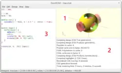
The OpenSCAD user interface (UI) starts with three sections showing:
- The Model Viewing Pane
- The Console Pane
- A Text Editor Tab
The rest of the sections in the UI may be shown by enabling them using the Window Menu.
The complete interface has three sections and 10 Panes, which this page will describe in full.
Model View Pane - Advanced
Preview and rendering output goes into the viewing area. The following sections go into
The model view is configured using the Setup Options on the View Menu, and in the View Pane toolbar.
Setup
The available rendering methods are OpenCSG
Render modes
OpenCSG (F9)
This method renders an image of a model very quickly, but as the complexity of the model rises it slows more than others.
The OpenCSG mode is set using menu View > Preview (F9) but needs to be "compiled" using menu Design > Preview (F5).
The OpenCSG library is used for generating the preview image of the model. It uses the OpenGL Z buffer to rapidly evaluate the appearance of objects without having to generate polygonal geometry. For example, when rendering a spherical dent in a cube, it first renders the cube on the graphics card, and then limits the rendering of the sphere to only those parts visible.
CGAL (Surfaces and Grid, F10 and F11)
The other rendering mode uses the Computational Geometry Algorithms Library (CGAL) to generate polygonal surfaces for the model's components, which delays the start of the actual rendering, but once done renders images faster than in OpenCSG, particularly for complex models. This becomes important when a sequence of images are needed for an animation.
Keys F10 and F11 enable CGAL mode but do not compile shapes into polygonal form.
The menu Design > Render (F6) is used to do that, and to then render an image in the Preview Pane.
Alternately the render() function may be used to "bake" a model into polygonal form, even in OpenCSG mode.
Navigation
The viewing area is navigated primarily using the mouse:
| Action | Icons | Description |
|---|---|---|
| rotating the view | Dragging with the left mouse button rotates the view along the axes of the viewing area. It preserves the vertical axis' direction.
Double-click the left button to set the point of rotation. | |
| ⇧ Shift + |
Dragging with the left mouse button when the shift key is pressed rotates the view along the vertical axis and the axis pointing towards the user. | |
| moving the viewing area | Dragging with the right mouse button moves the viewing area. | |
| zooming | Using the scroll wheel | |
| Dragging with the middle mouse button | ||
| ⇧ Shift + |
Dragging with the right or middle mouse button and the shift key pressed | |
| ⇧ Shift + | ||
| + and - | The keys + and - (Ctrl+[ and Ctrl+]) | |
| show/hide rotation center | Ctrl+3 | Turn on or off the graphic showing the center of rotation. (It is always in the center of the viewing area). |
| rotation reset | Ctrl+0 | Rotation can be reset using the shortcut Ctrl+0. |
| translation reset | Ctrl + ⇧ Shift+0 |
Translation can be reset using the shortcut Ctrl+⇧ Shift+0. |
Show Edges (Ctrl+1)
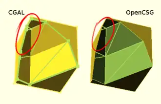
If Show Edges is enabled, both OpenCSG and CGAL mode render edges as well as faces; CGAL even shows vertices. In CGAL grid mode, this option has no effect.
Enabling this option shows the difference between OpenCSG and CGAL quite clearly: While in CGAL mode you see an edge drawn everywhere it "belongs", OpenCSG does not show edges resulting from boolean operations – this is because they were never explicitly calculated but are just where one object's Z clipping begins or ends.
Show Axes (Ctrl+2)
If Show Axes is enabled, the origin of the global coordinate system is indicated by an orthogonal axes indicator. Additionally, a smaller axes indicator with axes names are shown in the lower left corner of the viewing area. The smaller axes indicator is marked x, y, z and coloured red, green, blue respectively.
Show Crosshairs (Ctrl+3)
If Show Crosshairs is enabled, the center of the viewport is indicated by four lines pointing in the room diagonal directions of the global coordinate system. This is useful when aligning the viewing area to a particular point in the model to keep it centered on screen during rotation.
Console Output Pane - Advanced
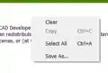
Right Click in the pane to see the operations that are possible:
- Clear
- removes the existing output text
- Copy
- enabled by selecting text in the pane
- Select All (Ctrl+A)dd
- to select all the text in the pane
- Save As...
- to save the text selected, or all of it
Text Editor Pane - Advanced
Editor Templates
The editor has a facility for pasting in blocks of text or snippets of code to assist when writing code. These text items are called Templates and are inserted into the script at the cursor position.
A few templates are installed with the app in [ResourcesPath]/templates and can be used as examples. The app will also look for templates in the folder [UserConfigPath]/templates, a place that a user can save templates into. This folder is not created by the application, see the Paths section for information about platform-specific paths.
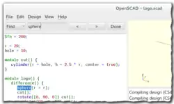
Using Templates
- Right-Click in the editor window to open the Context Menu
- Select the
Insert Templateitem on the menu - A pop-up opens showing the list of available templates
- Double clicking one of the names will cause its content to be pasted at the text cursor position (Note: Not at the location of the Step #1 Right Click).
For instance, selecting the "for" template will paste in the code for a for loop
for (i = [  :  ]) {

}
which comes from the for.json template file. (see Paths)
{
    "key" : "for",
    "content" : "for (i = [ ^~^ :  ]) {\n\t\n}"
}
This snippet sets the template's name as the key value, "for", and the content is a single string.
The "^~^" symbol marks the place the text cursor should be moved to allowing the writer to begin filling in the template.
The escape characters for newline, (\n) and tab (\t) are used for basic formatting of the content once pasted into place.
Each template file defines only one template and should follow the format of the "for" template just above.
There is (currently) no user interface for creating templates, but they are simple JSON files that may be created or modified using any text editor.
Note: Changes to a template will not be seen in any Editor Tabs already open, but will be visible in tabs opened after the update is saved.
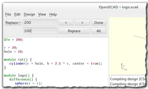
Interactive modification of a Numerical Value
It is possible to change a numeric value in the source code and observe the result in real time.
FIXME possible text
Increasing from 9 rolls over to zero, but also causes the left adjacent digit to increment to its next highest value which will ripple to the left most digit of that number. Likewise decrementing from zero causes the left adjacent digit to decrement as well, again rippling to the left end of the number. Digits to the right of the cursor are not affected.
The left and right arrows also have a role in interactive change
- left of a number
- use
Alt Left Arrowto add digits to the left - right of a number
Alt Right Arrowwill add a decimal point and one fraction digit per tap
With the Alt Key held down the left and right arrows will move the text cursor only within a number.
Placing the cursor after a digit and pressing Alt+ up arrow or Alt + down arrow will increment or decrement the chosen digit. The object is re-rendered and displayed in preview mode after each change of the selected number in the source code.
When the cursor is moved after the next digit by Alt + right arrow, the further decimal digits are added when needed by moving the cursor after the last digit on the right side. The cursor is moved left behind the most significant digits of the number by Alt + left arrow.
Placing the cursor to the right of a digit and pressing Alt+ up arrow or Alt + down arrow will increment or decrement it respectively.
When there is another digit to the left of the one being incremented, at the value "9" the digit to its left is incremented by 1 as the "9" is updated to "0".
Decrementing a number past zero will insert a minus sign, "-", to the left of the number.
When the cursor is at the right end of a number, pressing Alt + right arrow will insert a decimal point and a zero digit, moving the cursor after the zero.
Note: On MacOS, use Option + Shift instead of Alt.
| Key | Description |
|---|---|
| Alt+Up Arrow | Increment the numeric value to the left of the cursor and preview the object. |
| Alt + Down Arrow | Decrement the numeric value to the left of the cursor and preview the object. |
| Alt + Left Arrow | Move the cursor left to more significant digit. |
| Alt + Right Arrow | Move the cursor right to less significant digit, eventually add one more decimal digit. |
The Rest of the UI Features
Animation Control Pane
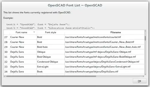
Fonts List Pane
Fonts are specified by their logical font name; in addition a style parameter can be added to select a specific font style like "bold" or "italic", such as:
font="Liberation Sans:style=Bold Italic"
The font list dialog (available under Help > Font List) shows the font name and the font style for each available font. For reference, the dialog also displays the location of the font file. You can drag a font in the font list, into the editor window to use in the text() statement.
OpenSCAD includes the fonts Liberation Mono, Liberation Sans, and Liberation Serif. Hence, as fonts in general differ by platform type, use of these included fonts is likely to be portable across platforms.
For common/casual text usage, the specification of one of these fonts is recommended for this reason. Liberation Sans is the default font to encourage this.
In addition to the installed fonts ( for windows only fonts installed as admin for all users ), it's possible to add project specific font files. Supported font file formats are TrueType Fonts (*.ttf) and OpenType Fonts (*.otf). The files need to be registered with use<>.
use <ttf/paratype-serif/PTF55F.ttf>
After the registration, the font is listed in the font list dialog, so in case logical name of a font is unknown, it can be looked up as it was registered.
OpenSCAD uses fontconfig to find and manage fonts, so it's possible to list the system configured fonts on command line using the fontconfig tools in a format similar to the GUI dialog.
$ fc-list -f "%-60{{%{family[0]}%{:style[0]=}}}%{file}\n" | sort

...
Liberation Mono:style=Bold Italic /usr/share/fonts/truetype/liberation2/LiberationMono-BoldItalic.ttf
Liberation Mono:style=Bold        /usr/share/fonts/truetype/liberation2/LiberationMono-Bold.ttf
Liberation Mono:style=Italic      /usr/share/fonts/truetype/liberation2/LiberationMono-Italic.ttf
Liberation Mono:style=Regular     /usr/share/fonts/truetype/liberation2/LiberationMono-Regular.ttf
...
Under Windows, fonts are stored in the Windows Registry. To get a file with the font file names, use the command:
reg query "HKLM\SOFTWARE\Microsoft\Windows NT\CurrentVersion\Fonts" /s > List_Fonts_Windows.txt
Example
_font_style_example.png)
 square(10);

 translate([15, 15]) {
   text("OpenSCAD", font = "Liberation Sans");
 }

 translate([15, 0]) {
   text("OpenSCAD", font = "Liberation Sans:style=Bold Italic");
 }
Customizer Pane
Viewport Control Pane
The menu items Top, Bottom, …, Diagonal and Center (Ctrl+4, Ctrl+5, …, Ctrl+0, Ctrl+Shift+0) align the view to the global coordinate system.
Top, Bottom, Left, Right, Front and Back align it in parallel to the axes, the Diagonal option aligns it diagonally as it is aligned when OpenSCAD starts.
The Center option puts the coordinate center in the middle of the screen (but not rotate the view).
By default, the view is in Perspective mode, meaning that distances far away from the viewer appear shorter, as seen in the real world eyes or cameras. When the view mode is changed to Orthogonal, visible distances do not depend on the camera distance (the view simulates a camera at an infinite distance with an infinite focal length). This is especially useful in combination with the Top etc. options described above, as these orthogonal views result in a 2D images similar to what one would see in an engineering drawing.